Introduction
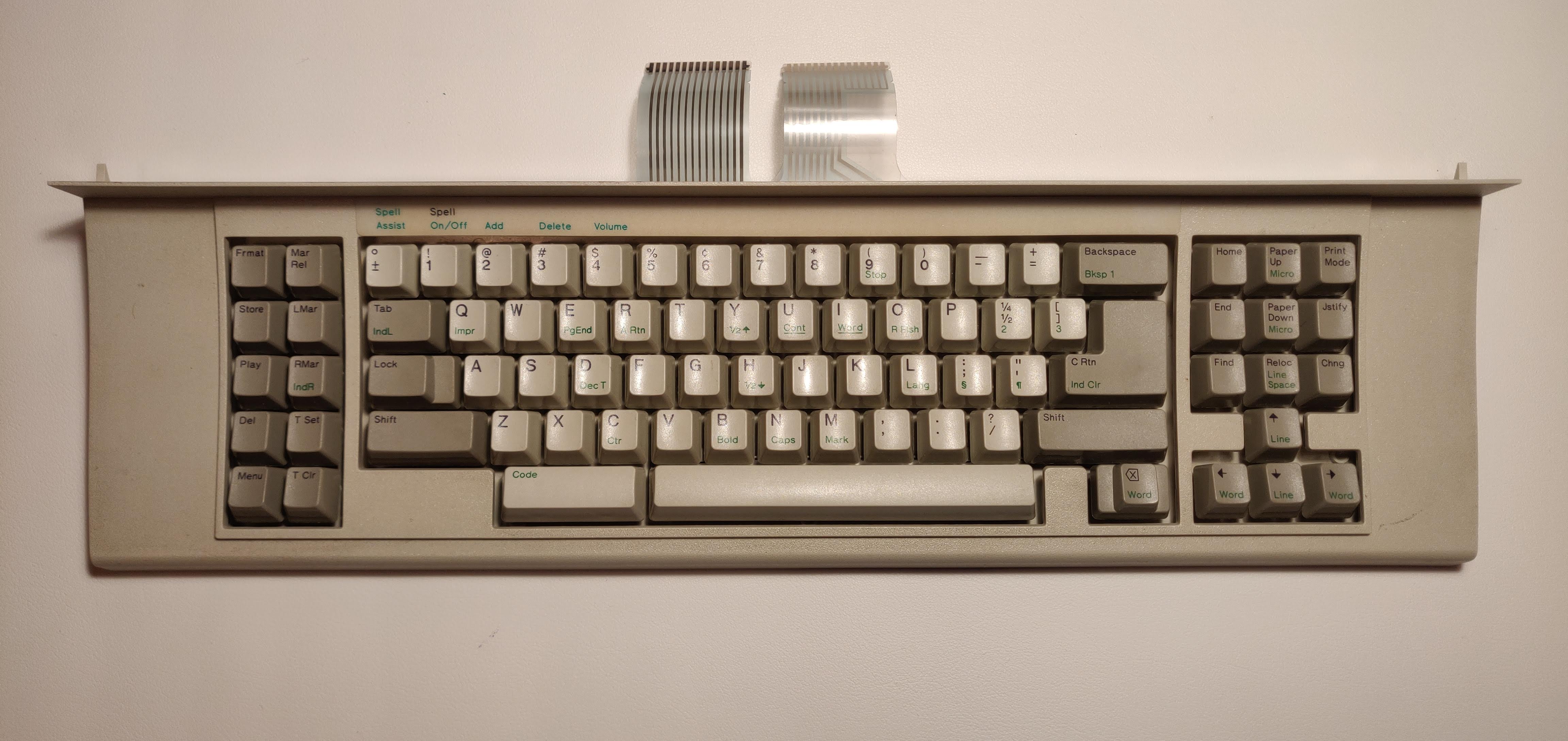
My friend and I bought an IBM Wheelwriter30 on a whim from the Purdue surplus store almost two years ago. We had vague ideas of refurbishing it, or at the very least taking the keyboard off and turning it into a USB keyboard using an Arduino. But, like so many other pipe dreams, the typewriter languished in my basement until I graduated and had to move out of my college house. I threw away the bulky typewriter machine but kept the keyboard. It had only two flexible printed circuit connectors, a manufacturing date of 1989 printed on the back, and absolutely no documentation.
Reverse engineer the matrix
This isn’t quite as challenging or as flashy as the section header might imply! What we want to do here is make sense of the two headers coming out of the keyboard so that we can program a micro-controller to understand the keyboard layout. The way engineers build a keyboard without having to make a wire for each key is to create a matrix (or grid) and detect key-presses based on their unique row & column combination. The creators of the QMK firmware wrote a good explanation, check it out here. So, based on the two headers coming out of the board we have a 14x8 matrix, or maybe that’s 8x14? I didn’t know how to orient the grid at first, but that’s okay. Labelling the deminsions rows and columns is arbitrary, and if the layout is sensible, it should be easy to tell which way is up once we know where things go. I used a multimeter to test for continuity and a spreadsheet to record my findings. Below is the keyboard matrix laid bare. There are some strange keys, but most are familiar!
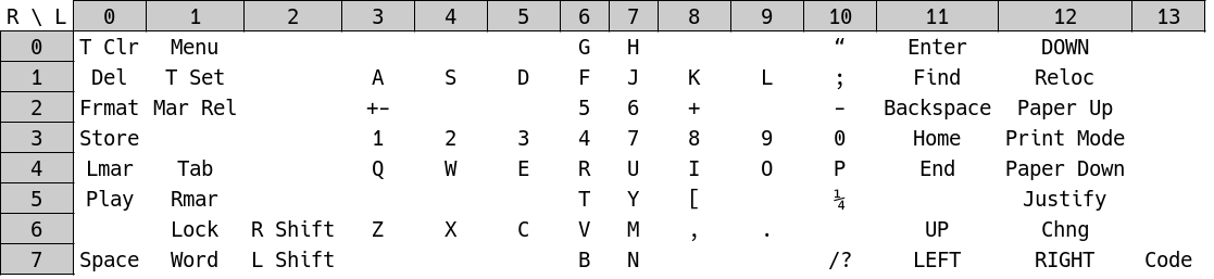
We can see that there are eight rows and fourteen columns. Most keys are in a sensible position, along row four we see Q-W-E-R, but T-Y has been shifted to row five. The matrix doesn’t have to be related to the key layout at all, but it will make the PCB design underneath the keys easier. Some keys that do matter are the shift and code keys, these are modifiers that are pressed down at the same time as other keys, so they get their own columns. Most modern mechanical keyboards have a diode for each key, but this keyboard doesn’t. The diodes prevent a phenomenon called ghosting, which creates phantom (or ghost) key presses when multiple keys are held down.
Translate the matrix into a keymap for QMK
The QMK firmware is impressivly configurable, and there are some frameworks we can use to help us translate the hardware key matrix into a sensible keymap that we can assign semantic meaning. What we can do is use the C compiler macro features to translate the keyboard hardware matrix into a key layout matrix. This will allow us to create an array that matches the actual layout of the keys, assign meaning to each key, and then translate those meanings into our hardware matrix. Let’s take a look at it, and then I’ll explain what’s happening.
#define LAYOUT( \
    K0A,K0B,  K0C,K0D,K0E,K0F,K0G,K0H,K0I,K0J,K0K,K0L,K0M,K0N,K0O,K0P,  K0Q,K0R,K0S, \
    K1A,K1B,  K1C,K1D,K1E,K1F,K1G,K1H,K1I,K1J,K1K,K1L,K1M,K1N,K1O,K1P,  K1Q,K1R,K1S, \
    K2A,K2B,  K2C,K2D,K2E,K2F,K2G,K2H,K2I,K2J,K2K,K2L,K2M,K2N,    K2P,  K2Q,K2R,K2S, \
    K3A,K3B,  K3C,K3D,K3E,K3F,K3G,K3H,K3I,K3J,K3K,K3L,K3M,                  K3R,     \
    K4A,K4B,      K4D,        K4G,                                K4P,  K4Q,K4R,K4S  \
  ) \
  { \
    {K4B,  K4A,  KC_NO, KC_NO, KC_NO, KC_NO, K2H,K2I,KC_NO, KC_NO, K2N,   K1P,   K4R, KC_NO}, \
    {K3A,  K3B,  KC_NO, K2D,   K2E,   K2F,   K2G,K2J,K2K,   K2L,   K2M,   K2Q,   K2R, KC_NO}, \
    {K0A,  K0B,  KC_NO, K0C,   KC_NO, KC_NO, K0H,K0I,K0O,   KC_NO, K0N,   K0P,   K0R, KC_NO}, \
    {K1A,  KC_NO,KC_NO, K0D,   K0E,   K0F,   K0G,K0J,K0K,   K0L,   K0M,   K0Q,   K0S, KC_NO}, \
    {K1B,  K1C,  KC_NO, K1D,   K1E,   K1F,   K1G,K1J,K1K,   K1L,   K1M,   K1Q,   K1R, KC_NO}, \
    {K2A,  K2B,  KC_NO, KC_NO, KC_NO, KC_NO, K1H,K1I,K1O,   KC_NO, K1N,   KC_NO, K1S, KC_NO}, \
    {KC_NO,K2C,  K2P,   K3D,   K3E,   K3F,   K3G,K3J,K3K,   K3L,   KC_NO, K3R,   K2S, KC_NO}, \
    {K4G,  K4P,  K3C,   KC_NO, KC_NO, KC_NO, K3H,K3I,KC_NO, KC_NO, K3M,   K4Q,   K4S, K4D  }  \
  }
So this is a pre-compiler directive, basically a find and replace, that takes many inputs and places them in a 2D array. The first half of the block of text has been formatted with spaces and new-lines to resemble the actual layout of the keys on the keyboard but it’s just a list of arguments to the macro. The second half of the #define is a 2D array that represents the electrical matrix of the keyboard. There are many row and column combinations that don’t represent any key, these are defined in the QMK firmware as KC_NO. The symbols we’ve used here don’t really matter, but they are named systematically, just for my own sanity. Below is an abridged version of the code as it appears when defining an actual layout. This is finally the step where we give keys semantic meaning. The #define statement above translates the text below into a 2D array that the firmware will understand.
uint16_t keymap[MATRIX_ROWS][MATRIX_COLS] = { LAYOUT(
KC_NO,KC_NO,KC_ESCAPE  ,KC_1,KC_2,KC_3,KC_4,KC_5,KC_6,KC_7,KC_8,   KC_9,  KC_0,   KC_MINS, KC_EQL, KC_BSPC,  KC_HOME,KC_PGUP,KC_PSCREEN,
KC_NO,KC_NO,KC_TAB     ,KC_Q,KC_W,KC_E,KC_R,KC_T,KC_Y,KC_U,KC_I,   KC_O,  KC_P,   KC_NO,   KC_LBRC,KC_ENTER, KC_END, KC_PGDN,KC_NO,
KC_NO,KC_NO,KC_CAPSLOCK,KC_A,KC_S,KC_D,KC_F,KC_G,KC_H,KC_J,KC_K,   KC_L,  KC_SCLN,KC_QUOTE,        KC_RSHIFT,KC_FIND,KC_NO,  KC_NO,
KC_NO,KC_NO,KC_LSHIFT  ,KC_Z,KC_X,KC_C,KC_V,KC_B,KC_N,KC_M,KC_COMM,KC_DOT,KC_SLSH,                                   KC_UP,
KC_NO,KC_NO,            CODE,          KC_SPACE,                                                   KC_DELETE,KC_LEFT,KC_DOWN,KC_RIGHT
)
Select the pins for the hardware matrix
We’ve got a good idea now how the keyboard operates internally, lets begin to plan out how we will interface a micro-controller with the keyboard. I chose to use the Proton C, an STM32F3 based micro-controller board that was designed to be used by keyboard enthusiasts. Almost any micro-controller can be used for a keyboard, but our lives will be much easier if we select a board that is known to work with QMK. The next step in configuring the QMK firmware is to tell it what pins on our micro-controller we will be using for the rows and columns. This is a little daunting, and also a little arbitrary. I looked around on GitHub for some examples of others who have used the Proton C in their keyboard builds and found this wonderful write-up by Andrew Dunai (GitHub user: and3rson). He went over some of the issues he had when using certain pins on the Proton C. I played it safe and created a list of pins that I could chose from the use for my rows and columns. Below are the pin assignments in my QMK configuration file.
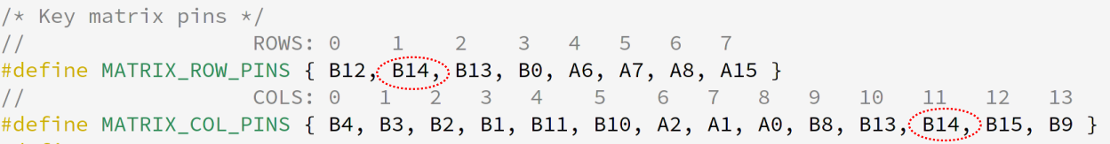
//                  ROWS: 0    1    2    3   4   5   6   7
#define MATRIX_ROW_PINS { B12, A14, A13, B0, A6, A7, A8, A15 }
//                  COLS: 0   1   2   3   4    5    6   7   8   9   10   11   12   13
#define MATRIX_COL_PINS { B4, B3, B2, B1, B11, B10, A2, A1, A0, B8, B13, B14, B15, B9 }
At first they seem random, but their ordering is designed to make it easy to route a PCB with the Proton C mounted to it. Let me show you.
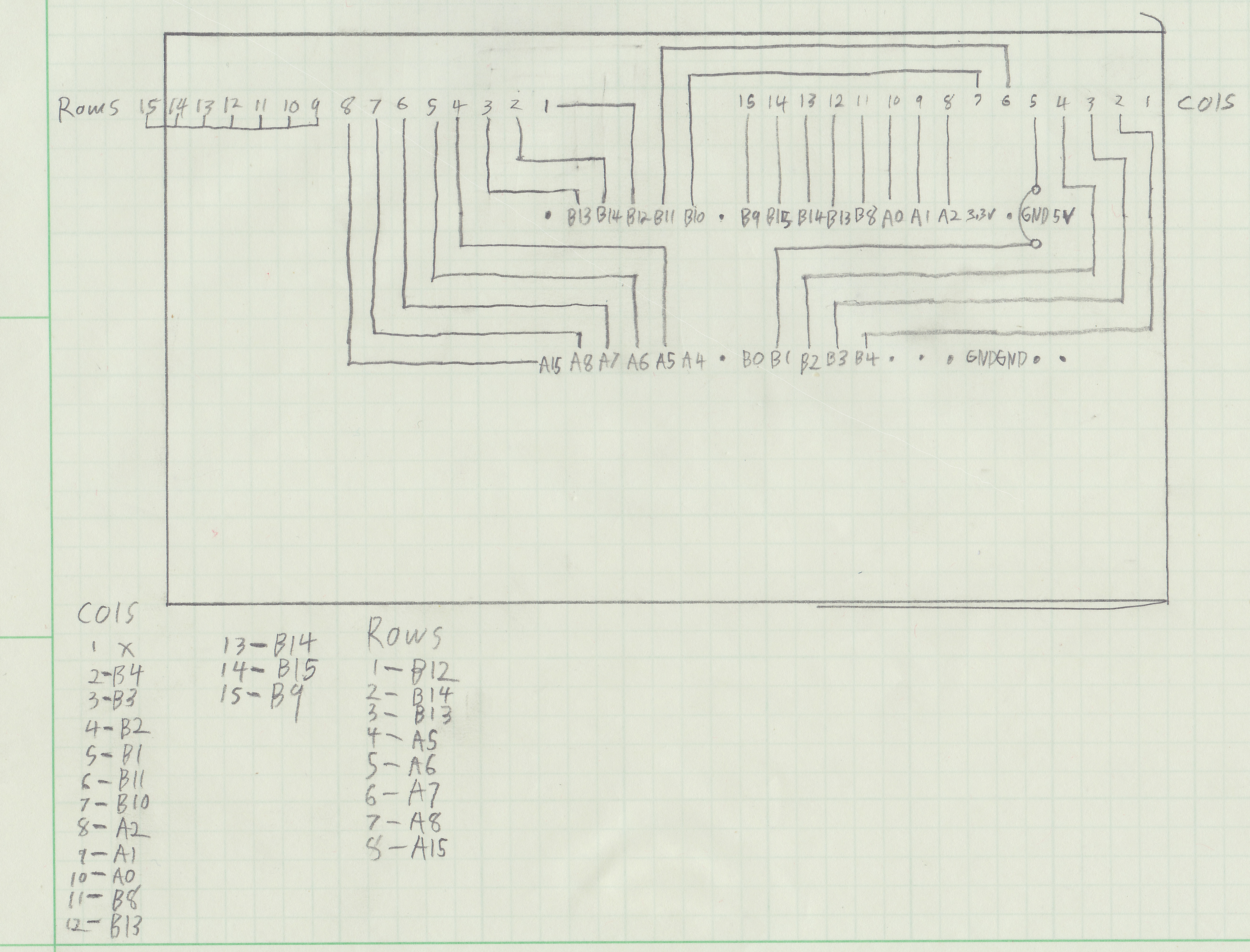
Now things are much easier to see. There is a method in the madness! It’s finally time to start building. We have layers of abstraction and syntax that will take us all the way from these electrical connections to the Latin alphabet. All that is left is to bridge this last metallic gap, and we can express thoughts using this keyboard for the first time in decades.
Solder, test, debug repeat!
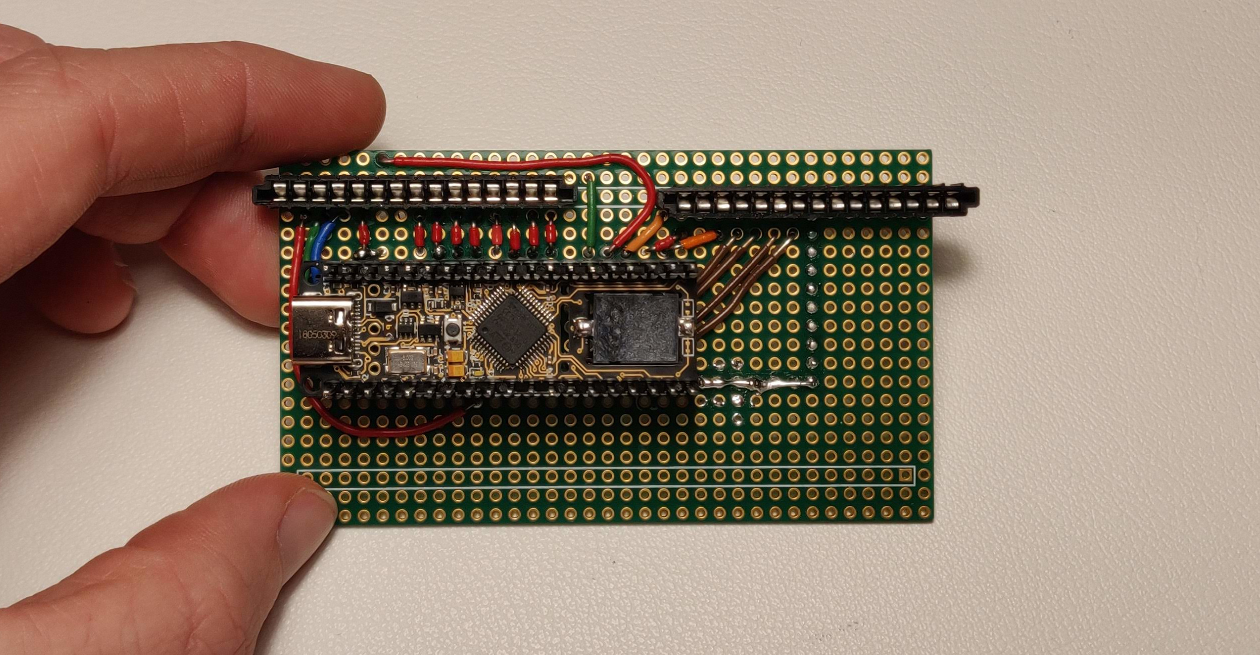
This is it! This is the thing that I’ll plug the keyboard and a computer into, and hopefully this board will translate one to the other. Well, as you can guess, it didn’t work quite right the first time.
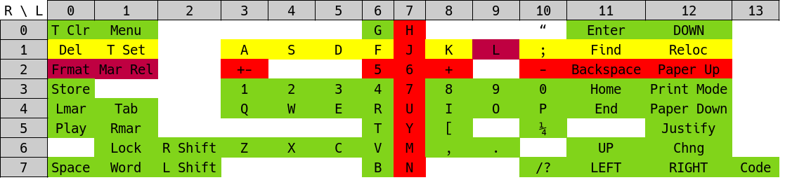
After a few hours of soldering, I had connected up every row and column, and even tested each connection with a multi-meter, but still, something was wrong. Most keys worked alright, some didn’t work at all, and others would print many different letters at once! Failure is a part of every project. Nobody writes bug free code, and nobody builds perfect proto boards. Reliability in hardware is just experience with having it break in many different ways, and fixing each one. So I went about finding the source of my issue methodically. I tested each key and plotted their behavior in a spreadsheet. Green is all good, yellow printed every letter in the column of the key pressed, and red did nothing at all.
There could be one or more errors in three domains, the keyboard itself, the proto board I just soldered, and the code running on the micro-controller. Thankfully there wasn’t an issue with the decades old keyboard, because I’m not sure I could take it apart and fix an issue on flexible printed plastic circuits! I double checked the code, and low and behold I found a typo. I had accidentally assigned the same pin to a row and a column! I had just mixed up a B for an A. I’m honestly shocked the code compiled and that any keys worked at all. I’m not certain what was going on with pin B14, but I think it may have been toggling between input and output modes thousands of times per second. I’m just happy that the micro-controller wasn’t damaged.
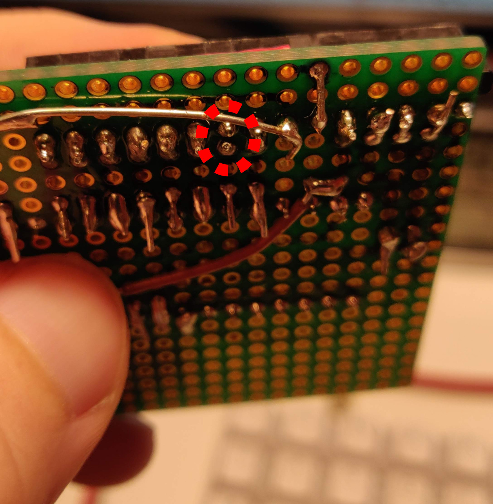
After a quick consult to figure out which B14 was the impostor, and with a new version of the firmware running on the micro-controller, things were looking better. Most keys now worked correctly, but column seven was still simply dead. This at this point I’d checked the code, and checked each connection one by one with a multi-meter, so things were starting to look grim for the success for the project. If there was a tiny crack in the plastic circuit board on column seven inside the keyboard, I would have little hope of fixing it. So I began looking closer at column seven on the proto board. After a few minutes of head scratching I saw it, a small air gap between two pins where I had forgotten to solder. I was testing with the board upside-down, and so I was probing the connection with the multi-meter in such a way as to avoid detecting the problem. Look below to the image and see that small gap! Fixing column seven was no problem, just a small solder bridge solved the issue entirely.
Finally, at long last, the keyboard works! I can loudly clack away on a keyboard built for a typewriter in the 1980’s. It’s even got an embedded speaker and plays a little startup jingle that my brother composed for me.
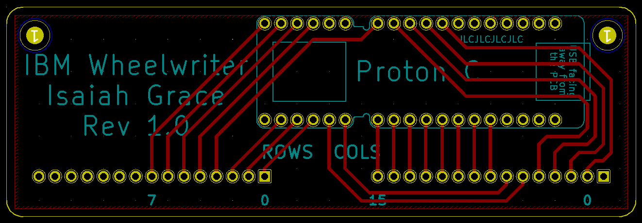
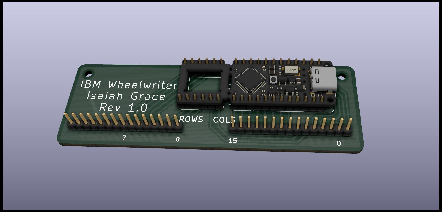
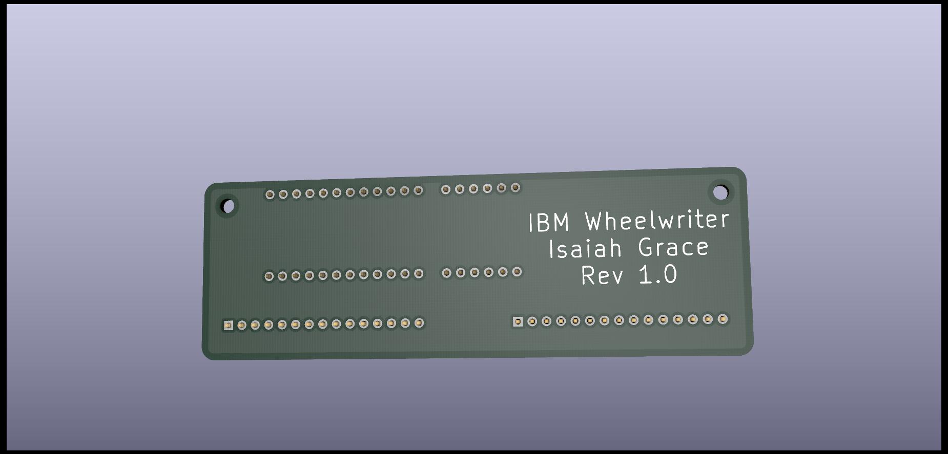
Design a real PCB
About a month after I completed the proto board, I wanted to practice my KiCad PCB skills, and I selected this project as a great option for a simple PCB layout. It’s dead simple, just a bunch of pin headers connected together, no other components. While I was waiting for the board to arrive from the factory, I put together some renders on KiCad showing off the design and some 3D models of the Proton C, courtesy of the QMK firmware team.